J-IVS / J-IV / J-IVL
Prior to Commencing:
All installations should be in line with Installation Manuals, Design & Technical Manuals and the Project Selection document specific to the system you are installing. Have all pipe lengths measured—not guessed.
Please Note: The information in this guide is subject to change.
1. Power Wiring
1.1. Ensure all indoor and outdoor units are safely powered.
1.2. Confirm all wired controllers are powered and have display.
1.3. When power is applied initially to indoor units, Operation and Timer lights will flash alternately.
1.4. Rectify any power or wiring issues prior to attempting addressing.
2. Transmission Wiring
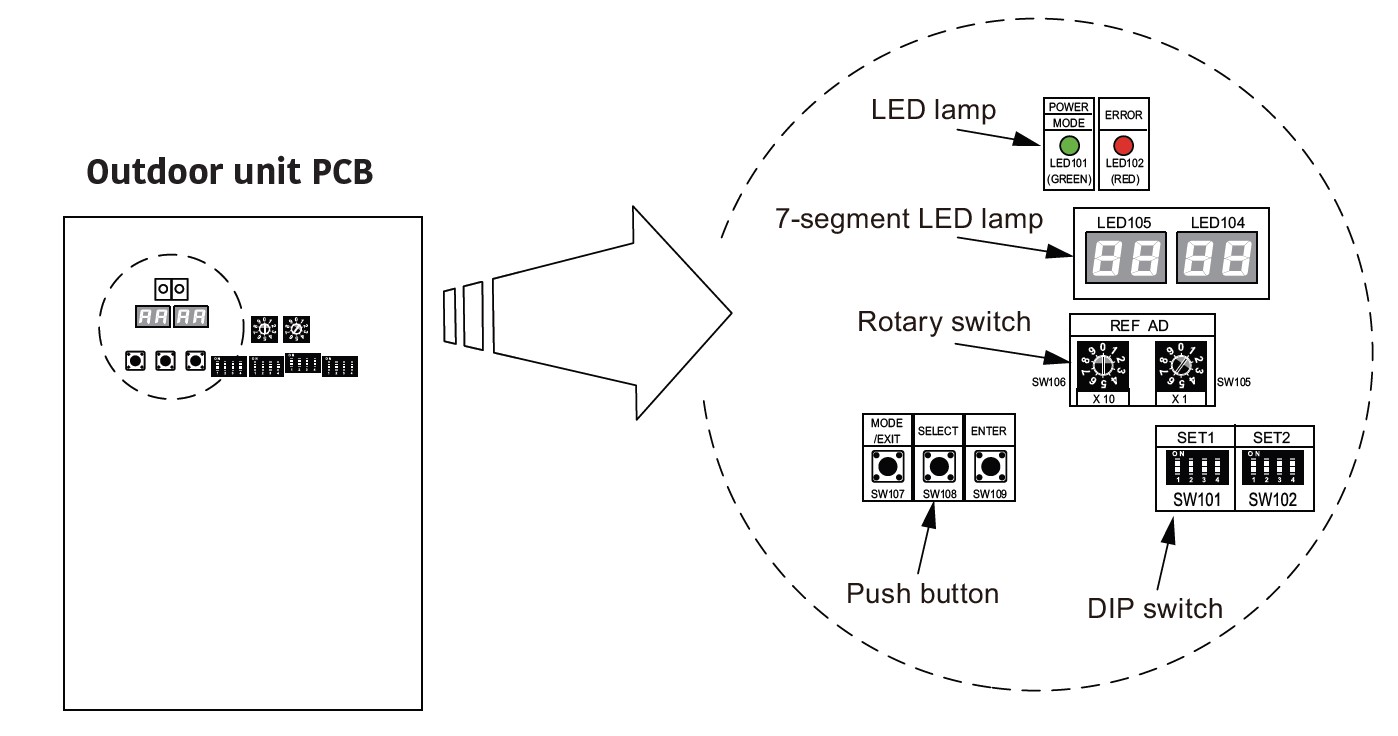
2.1. Confirm terminal resistor is set (for all single VRF systems, DIP SW 5-4 should be ON on the outdoor unit).
2.2. DIP SW 5-4 is ON from factory for all J series units. For sites with multiple VRF systems with any common transmission line link, refer to the terminal resistor requirements.
2.3. Ensure the correct cable has been used.
2.4. Transmission wiring runs from outdoor unit X1,X2 terminals to every indoor unit on the system via daisy chain.
2.5. No star connections, there should be approx. 55 ohm across X1,X2 if wired correctly and terminal resistor is set.
2.6. In the event of multiple VRF systems on-site, connection between the Master outdoor units should be using Z1,Z2 terminals.
Please Note: Before commencing test run or system operation, ensure drains are connected.
3. Outdoor Unit Addressing
3.1. You must set a unique refrigerant (REF) address for each outdoor unit on site.
3.2. This is factory set to 00 which is suitable for sites with a single VRF system.
3.3. For sites with multiple systems, set to REF 01 for the first outdoor unit, REF 02 for the second outdoor unit onsite.

4. Indoor Unit Auto Addressing
4.1. Press MODE / EXIT button on outdoor PCB once. F1 will flash.
4.2. Press SELECT button to cycle to F3, press ENTER.
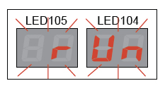
4.3. Press SELECT button to cycle to 11 on the LED display, hold ENTER for 3 seconds or longer to initiate Automatic Addressing function -- “run” will display when the connection check has commenced.

4.4. When automatic addressing is completed, LED105 will show the number of indoors successfully addressed. LED104 will show the number of indoor units which setting failed.
For a system with 7 indoor units, this should show on LED105 as 07 and on LED104 as 00.
4.5. If automatic addressing has failed, this is likely because some indoor units have been manually addressed, or because of a wiring or power issue, or an indoor unit is operating. You can re-initiate once the issues have been addressed.
4.6. When all units are successfully addressed, press ENTER. The LED panel will flash for about 30 seconds while the system finishes processing the command.
4.7. Power reset all indoor units for 2 minutes to ensure address is set.

5. Indoor Unit Capacity / Connection Check
5.1 Press MODE / EXIT button on outdoor PCB once. F1 will flash
5.2. Press SELECT button to cycle to F3, press ENTER.
5.3. Press SELECT button to cycle to 12 on the LED display, hold ENTER for 3 seconds or longer to initiate Indoor Unit Connection Check function— “run” will display when the connection check has commenced.
5.4. When the process has completed, the display on LED 104 and LED 105 will display how many units have been detected.
5.5. Verify this count matches the number of indoor units on the system.
5.6. While the indoor unit count is displayed on screen, press SELECT to change display to the ratio of indoor units.
5.7. Verify that the indoor unit count and connection ratio looks correct in line with the system design, press ENTER to proceed, LED display will change to PASS.
5.8. If the result is PASS, press ENTER to exit connection check and then press MODE/EXIT to exit function mode.
5.9. If the display shows Err. Then the indoor unit connection check has found an error, the display will alternate showing Err. and the number of errors.
5.10. To view the error details push ENTER, when there are multiple errors press SELECT to switch between them.
Indoor Unit Capacity / Connection Check - Error Examples

6. Terminal Resistor Configuration
6.1. There must be one (1) terminal resistor set on the VRF wiring network to ensure correct communication. Fujitsu Airstage VRF J Range Outdoor units all have terminal resistor set on the outdoor unit from factory.
6.2. When you have multiple systems on one site:
- • If the units do not have a common transmission wiring network with other systems, leave Terminal Resistor on for all outdoor units.
- • If there is a common transmission wiring network, leave Terminal Resistor on on ONE outdoor unit on the network and turn off Terminal Resistor on all the other outdoor units. There should only be one Terminal Resistor on when multiple outdoor units are on a common transmission wiring network.
7. Calculate Additional Refrigerant
7.1. You need MEASURED not estimated liquid line lengths to calculate additional refrigerant charge.
7.2. Every VRF system requires additional refrigerant, these systems are pre-charged to zero metres of pipe run.
7.3. The calculation can be found on the outdoor unit electrical box cover or in the installation manual.
7.4. To calculate additional refrigerant charge, determine the length in metres for each liquid line diameter (6.35mm, 9.52mm and 12.70mm) then refer to the calculation formula in the manual / charge calculation table.
7.5. Round up this figure to 2 decimal places.
7.6. Ensure you write the calculation and additional charge information on the panel on the outdoor unit - this information is often required in the future.
8. Adding the Refrigerant Charge
8.1. Do not open service valves or add refrigerant until the system has been evacuated. Ensure the system is holding 500 microns or below with the pump isolated.
8.2. Additional refrigerant charge should be added into the field piping.
9. Initiate Test Run from Outdoor Unit
9.1. Press MODE / EXIT button on outdoor PCB once. F1 will flash.
9.2. Press SELECT button to cycle to F3, press ENTER.
9.3. Use SELECT to cycle on the LED display through different options, hold ENTER for at least 3 seconds to initiate while on the desired setting.
9.4. Cooling Test Run = F3 > 00, Heating Test Run = F3 > 01, Stop Test Run = F3 > 02.
9.5. Once test run is activated, display will show DONE and will revert to flashing previous screen. Press MODE / EXIT to return to monitoring display.
9.6. While in Monitoring display, LED will display CL when running in Cooling, HT when running in Heating.
9.7. Test run will run for 60 minutes and then automatically shut off. You can manually stop test run. Navigate to F3 > 02 and then hold ENTER for 3 seconds.
10. Review and configure function settings
10.1. You should always review the function settings and ensure that all indoor and outdoor units are configured to suit the site requirements. The function settings for each model can vary, so always refer to the specific manual for the unit being configured.
10.2. For heat pump systems, factory settings are that the first indoor unit on determines heating or cooling cycle - To switch between modes, turn off all indoor units (please allow 2-3 minutes to ensure the outdoor unit has registered all units are off), switch mode, then turn on the desired indoor units.
10.3. A common preference is to determine a Master Indoor Unit to determine the mode between heating and cooling. To do this: set outdoor unit F2-21 to 02 (00 = first command, 01 = external input, 02 = Master Indoor Unit). Master indoor unit must be configured to enable AUTO mode on the unit desired to be the master unit.
10.4. Once the outdoor unit is set, use the desired indoor unit controller to select the master indoor unit. (Menu > Initial Setting > Master Indoor Unit Setting – please refer to the relevant controller’s installation manual for further details).
10.5. For ducted indoor units, review the static pressure options in the install manual and set to suit the installation using indoor unit function 26 - refer to the manual for settings per model.
10.6. Other common functions to consider changing are Filter Status indicator (13) and Auto Restart (40) review the installation manuals for full details for your units.
Need Additional Support?

For additional VRF Commissioning support, get in touch with our Fujitsu General Australia technical support team.
- Phone: 1300 364 484
- Online: Click Here to Submit a support ticket via our Contact Us page


